Posterior shoulder instability is usually caused by traumatic posterior dislocation or repetitive minimally invasive injury during exercise or other activities, with an annual incidence rate of 4.64 cases per 100000 people per year. Several surgical techniques for the treatment of posterior shoulder instability have been described, including soft tissue repair and open and arthroscopic bone block surgery. However, the reported surgical complications and revision rates were as high as 14% and 67%, respectively. In particular, accurate placement of bone grafts, screw orientation and treatment of concomitant lesions are considered challenging. Therefore, surgical techniques need to be improved.
Operation steps:
The operation was performed under general anesthesia combined with regional block of intermuscular sulcus.
For iliac crest collection, local anesthetics were applied subcutaneously and periosteally.
The patient was placed in a beach chair with the back at a 45 ° angle to allow full contact with the iliac crest. After the bone transplantation was harvested, the operation continued, and the patient was sitting at an angle of 70 °. The patient was suspended in a standard sterile manner, and the operating arm was bent forward 30 ° through a 2 to 3 kg traction rope.
Arthroscopic joint evaluation
This procedure uses two or three entrances. The first front (E) entrance can be used for thorough joint exploration.
Ranges can be introduced directly into joints through rotator intervals. In some cases, it is impossible to directly introduce the scope (i.e., scar tissue around the rotator interval).
You can create a lateral C entrance or a front lateral D entrance, so that you can enter the space under the acromion peak, so that you can observe the rotator muscle space.
Arthroscopic radiofrequency ablation was used to open the rotator interval.
The toggle lever is positioned in the joint through the E entry to switch the range to the joint interior view.
After a comprehensive evaluation of the joint, the soft tissue lesions and associated lesions of glenoid and humeral bone loss (i.e., posterior glenoid lip, joint capsule, glenoid marginal lesion and reverse Hill Sachs lesion) were evaluated.
After thorough arthroscopic evaluation of the glenohumeral joint and confirmation of appropriate indications, bone grafts were obtained.
Bone transplantation harvesting and preparation
The bicortical autograft was obtained from the ipsilateral anterior iliac crest to preserve the inner cortex of the pelvis. Make skin incision about 2cm behind the anterior superior iliac spine and 2cm below the crest along the iliac crest to avoid scar formation that directly covers the crest.
After observing cortical bone α and β Two parallel Kirschner pins were inserted into the lateral cortex through the hole, which was previously equipped with two long coracoid screws from the Arthroscopic Latarjet device (Fig. 1).
The handle of the guide is oriented upward so that the bone graft can be anatomically matched with the posterior inferior glenoid neck. The placement of the guide allows the selection of the upper ridge as the articular side of the bone block.
Then, push the hollow coracoid process step drill on the Kirschner wire and drill two 2.9mm holes in the bone block. The drill bit and the Kirschner pin were removed. Before inserting the top cap washer into the drill hole, tap the hole with the top cap tap.
Once the top cap is in place, use a swing saw or bone knife to preserve the medial cortex of the iliac crest and harvest 2-cm × 1-cm × 1-cm grafts (Figures 2 and 3). After the graft is harvested, the bone block is connected to the coracoid process sleeve and two long hollow coracoid process screws are used to form a unit that can be manipulated to its final position (Fig. 4).
The iliac crest wound was closed layer by layer with drainage tube and dressing was used. Then adjust the back of the operating table to an angle of 70 °.
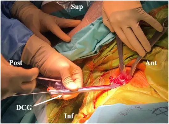
Figure 1. The right iliac crest bone was collected when the patient was in the beach chair position. The two Kirschner needles are positioned together with the double cannula guide device, and the handle of the cannula is upward. (Ant, front; DCG, double casing guide; Inf, lower Post, rear; Sup, upper.)
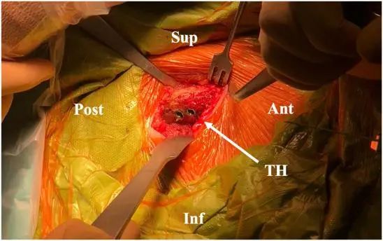
Figure 2. When the patient is in the beach chair position, the bone block of the right iliac crest is taken. Remove the drill bit and Kirschner wire after drilling the lateral platform of the iliac crest cortex, and then insert 2 "hats". (Ant, front; DCG, double casing guide; Inf, lower; Post, rear; Sup, upper; TH, top hat.)
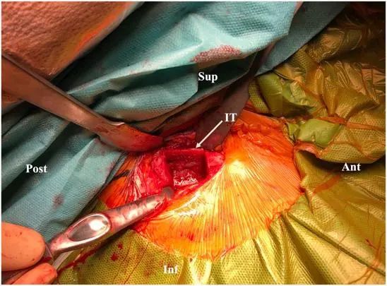
Figure 3. When the patient is in the beach chair position, the bone block of the right iliac crest is taken. The internal surface of the iliac crest remains intact after the graft is harvested. (Ant, front; Inf, bottom; IT, inner table; Post, back; Sup, top.)
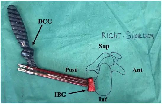
Figure 4. Prepare bone blocks on the side table. After the graft was harvested, the bone graft was connected to the double cannula using two cannula obturators. (Ant, front; DCG, double cannula guidance; IBG, iliac bone transplantation; Inf, lower; Post, rear; Sup, upper.)
Rear road signs and access roads
Usually two to three channels are used. The purpose is to align the posterior A inlet with the glenohumeral joint line as much as possible. Therefore, it is controlled by the arthroscope. Therefore, it is mainly performed after the operation from the front lateral inlet.
The anterolateral entrance E is placed in the rotator muscle space above the biceps muscle, which can perfectly display the posterior part of the glenoid edge (Table 1).
In most cases, no more channels are needed; However, if necessary, an additional posterolateral B inlet through the rear cuff can be used (for example, to manage complementary labial prostheses).
Ideally, Entrance A is located exactly on the axis of the glenohumeral joint line.
Through the front and rear view of the entrance E, insert 2 spine needles back at a distance of 2.5 to 3 cm, and insert the joint in parallel at the 7 o'clock and 9 o'clock positions (right shoulder).
Make a skin incision between the 2 needles and use it as the rear A entrance (Figures 5A and B).
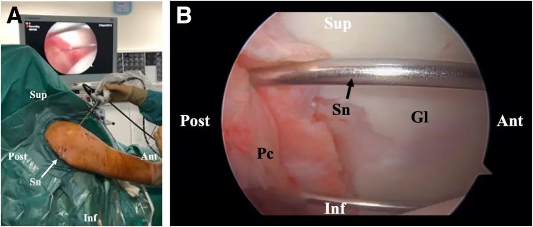
Figure 5. (A) The patient shall mark and prepare the skin incision in the 70 ° angle sitting position, right shoulder and E entrance view. In order to achieve the best alignment between the rear A inlet and the glenohumeral joint line, two spine needles are inserted backward to determine the sign of the skin incision.
(B) Arthroscopic visualization, right shoulder, and electronic portal view of the patient with the needle in a 70 ° sitting position. (Ant, anterior; DCG, double cannula guidance; Gl, glenoid; Inf, inferior; Post, posterior; Pc, posterior capsule; Sn, spinal needle; Sup, superior.)
Glenoid preparation
The instrument is introduced through the rear (A) inlet.
Remove the labrum and posterior capsule from 7 to 10 (right shoulder) using the VAPR and razor (Fig. 6A and B, Video 1).
Grind the posterior glenoid neck with arthroscopic burrs until the bleeding bone is exposed and the plane is prepared (Fig. 7). Once the glenoid neck is ready, the posterior A inlet is enlarged to allow passage of the graft and double coracoid cannula.
The scalpel can be used to expand muscle division and cystotomy, while the blunt rectangular trocar (subscapular passage) can be used to further expand the passage (Figure 8).

Figure 6. (AB) Visualization of glenoid preparation under arthroscopy, patient sitting at 70 ° angle, right shoulder, electronic entrance view. During the preparation of the glenoid, use VAPR and a razor to detach the glenoid lip and posterior capsule from 7:00 to 10:00. (Ant, anterior; Gl, glenoid; Hh, humeral head; Inf, inferior; Pc, posterior capsule; Post, posterior; Sup, superior; V, VAPR.)
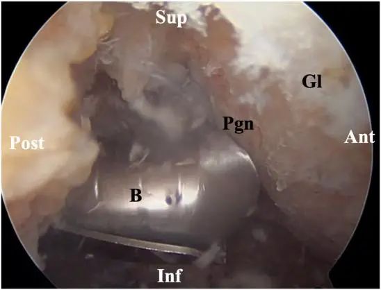
Figure 7. Arthroscopic visualization of glenoid preparation: the patient sat at an angle of 70 °, right shoulder, E-portal view. Wear of the posterior glenoid neck during glenoid preparation. (Ant, front; B, burr; Gl, glenoid; Inf, lower; Pgn, posterior glenoid neck; Post, rear; Sup, upper.)
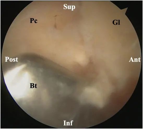
Figure 8. Arthroscopic visualization of glenoid preparation: the patient sat at an angle of 70 °, right shoulder, E-portal view. Enlarge the rear A inlet with a blunt trocar. (Ant, front; Bt: blunt trocar; Gl, glenoid; Inf, lower; Pc, posterior capsule; Post, posterior; Sup, upper.)
Graft positioning and fixation
The graft was inserted through the posterior entrance with the handle facing up (Fig. 9) and split through the muscle and joint capsule until it was close to the neck of the posterior glenoid and flush with the articular surface of the glenoid. This step needs to focus on the preparation of splitting, especially opening the thick and strong infraspinatus fascia and preventing the passage of the graft.
It is important to use the scalpel blade to open the fascia extensively. If necessary, in the later stage of surgery, if the flushing leakage is too important to maintain sufficient pressure on the shoulder, instruments can be used to partially close the surgical wound (for example, wound clips).
The coracoid cannula is placed parallel to the articular surface so that subsequent Kirschner wires and screws do not penetrate the joint during insertion.
Two 1.5 mm long Kirschner wires were inserted through the hollow coracoid process screws to fix the graft on the posterior glenoid neck (Fig. 10).
The insertion of the Kirschner wire should not exceed 40mm to avoid passing through the anterior glenoid neck, which may damage the anterior neurovascular structure, although only part of the subscapularis muscle exists between the neck and the neurovascular structure to protect it.
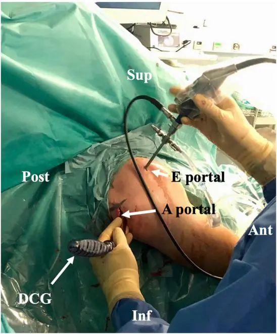
Figure 9. The patient inserted the graft in a 70 ° sitting position, and observed the right shoulder and posterolateral side. The graft was inserted through the rear entrance with the handle facing the top. (Ant, front; DCG, double casing guide; Inf, lower; Post, rear; Sup, upper.)
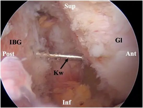
Figure 10. Arthroscopic visualization of graft positioning, patient sitting at 70 ° angle, right shoulder, E entrance view. Two inserted Kirschner pins stabilize the graft on the posterior glenoid neck. (Ant, front; Gl, glenoid; IBG, iliac bone graft; Inf, lower; Kw, Kirschner wire; Post, rear; Sup, upper.)
Since the 30 ° arthroscope is viewed from the front of the portal vein, it naturally tends to tilt the graft to an angle, making the lower surface prominent rather than straight. It is important to check whether the bone graft is still feasible after the graft placement.
Once the graft is flush with the posterior glenoid margin, remove the first long coracoid screw and drill a 3-2mm wide bicortical glenoid tunnel on the Kirschner wire.
In this step, it is important to remain still after the first practice. Auxiliary personnel must maintain with both hands (Figure 11).
It must be prepared to put the third Kirschner pin into the hole, because a Kirschner pin in its original position is usually caught in the motor involuntarily by the drill bit.
Care must be taken not to remove the Kirschner wire when pulling out the drill bit through the coracoid sleeve. Then, insert the 4.5 mm partially threaded Latarjet screw into the Kirschner wire (Fig. 12) and fully insert it to prevent the graft from shifting, and then drill the upper screw. Ideally, the screw length should not exceed 32 to 36 mm.
Any length greater than 40 mm requires careful examination, as this may be due to the steep angle of the graft relative to the glenoid surface, which may lead to graft dislocation. At this stage, the level of graft positioning can still be corrected by rotating the glenoid around the lower screw.
After inserting the first (lower) screw, the first Kirschner pin can be removed. Insert the second screw in the same way.
After inserting 2 screws and removing the Kirschner wire, use the probe at Entrance A to check the final graft position (Figure 13). Any protruding parts of the graft should be trimmed with burrs, and no soft tissue repair should be performed to prevent joint stiffness.
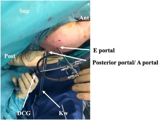
Figure 11. The graft was positioned and fixed. The patient sat at an angle of 70 ° with his right shoulder viewed from above. During and after the implant drilling, keep the guider still with both hands to prevent the K line from loosening the tunnel. (Ant, front; DCG, double cannula guidance; Kw, Kirschner wire; Post, rear; Sup, upper.)
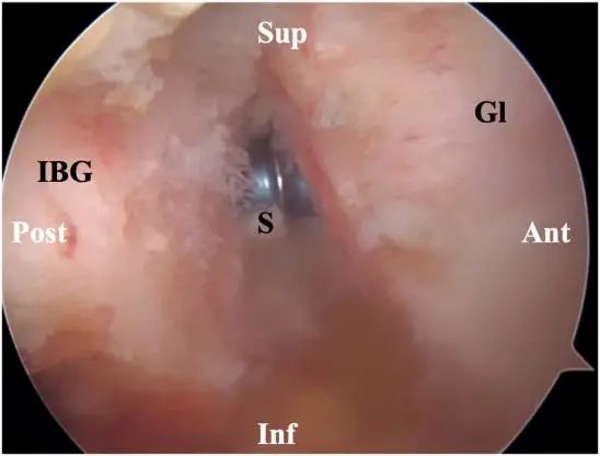
Figure 12. Arthroscopic visualization of graft fixation, patient sitting at 70 ° angle, right shoulder, electronic entrance view. The lower 4.5mm partially threaded Latarjet screw is first located above the Kirschner pin. (Ant, front; Gl, glenoid; IBG, iliac bone graft; Inf, lower; S, screw; Post, rear; Sup, upper.)
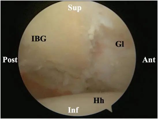
Figure 13. Arthroscopic visualization of graft positioning, patient sitting at 70 ° angle, right shoulder, E entrance view. After inserting two screws and removing the Kirschner wire, check the final transplant position. This kind of bone graft has good compressibility and no proud position. (Ant, anterior; Gl, glenoid; Hh, humeral head; IBG, iliac bone graft; Inf, lower; Post, posterior; Sup, upper.)
After surgery, the shoulder was fixed with 20 ° abduction angle and neutral rotation for 6 weeks:
The next day after the operation, start passive shoulder, elbow and hand range of motion exercise. Pronation and painful movements should be avoided.
At 3 weeks, start active range of motion exercises.
After the stability of the graft is confirmed by taking photos 6 weeks after the operation, intensive exercise can be started.
For athletes seeking rapid recovery, computerized tomography should be performed 3 months after surgery to assess graft integration.
How to Buy Orthopaedic Implants and Orthopaedic Instruments?
For CZMEDITECH, we have a very complete product line of orthopedic surgery implants and corresponding instruments, the products including spine implants, intramedullary nails, trauma plate, locking plate, cranial-maxillofacial, prosthesis, power tools, external fixators, arthroscopy, veterinary care and their supporting instrument sets.
In addition, we are committed to continuously developing new products and expanding product lines, so as to meet the surgical needs of more doctors and patients, and also make our company more competitive in the whole global orthopedic implants and instruments industry.
We export worldwide, so you can contact us at email address song@orthopedic-china.com for a free quote, or send a message on WhatsApp for a quick response +86-18112515727.
If want to know more information,click CZMEDITECH to find more details.
English
Français
Русский
Español
العربية
Português
Deutsch
italiano
日本語
한국어
Nederlands
Tiếng Việt
ไทย
Polski
Türkçe
አማርኛ
ພາສາລາວ
ភាសាខ្មែរ
Bahasa Melayu
ဗမာစာ
தமிழ்
Filipino
Bahasa Indonesia
magyar
Română
Čeština
Монгол
қазақ
Српски
हिन्दी
فارسی
Kiswahili
Slovenčina
Slovenščina
Norsk
Svenska
українська
Ελληνικά
Suomi
Հայերեն
עברית
Latine
Dansk
اردو
Shqip
বাংলা
Hrvatski
Afrikaans
Gaeilge
Eesti keel
Māori
नेपाली
Oʻzbekcha
latviešu
অসমীয়া
Aymara
Azərbaycan dili
Bamanankan
Euskara
Беларуская мова
भोजपुरी
Bosanski
Български
Català
Cebuano
Corsu
ދިވެހި
डोग्रिड ने दी
Esperanto
Eʋegbe
Frysk
Galego
ქართული
guarani
ગુજરાતી
Kreyòl ayisyen
Hausa
ʻŌlelo Hawaiʻi
Hmoob
íslenska
Igbo
Ilocano
Basa Jawa
ಕನ್ನಡ
Kinyarwanda
गोंगेन हें नांव
Krio we dɛn kɔl Krio
Kurdî
Kurdî
Кыргызча
Lingala
Lietuvių
Oluganda
Lëtzebuergesch
Македонски
मैथिली
Malagasy
മലയാളം
Malti
मराठी
ꯃꯦꯇꯥꯏ (ꯃꯅꯤꯄꯨꯔꯤ) ꯴.
Mizo tawng
Chichewa
ଓଡ଼ିଆ
Afaan Oromoo
پښتو
ਪੰਜਾਬੀ
Runasimi
Gagana Samoa
संस्कृत
Gaelo Albannach
Sepeti
Sesotho
chiShona
سنڌي
Soomaali
Basa Sunda
Wikang Tagalog
Тоҷикӣ
Татарча
తెలుగు
ትግንያውያን
Xitsonga
Türkmençe
संस्कृत
ئۇيغۇرچە
Cymraeg
isiXhosa
ייִדיש
Yorùbá
isiZulu


